

You press the button on the wall, and nothing happens. Or worse, the door starts to go down, shudders, and reverses right back up, blinking its light at you like it’s mocking your schedule. We’ve all been there. It’s frustrating when your garage door acts up, especially when you’re rushing to leave for work or trying to get inside after a long day.
Often, the culprit is those little safety eyes near the floor. They get bumped by bikes, coated in dust, or simply wear out over time. While checking alignment is easy enough, knowing if the electrical signal is actually working is a different story. That’s why learning how to test garage door sensors with multimeter tools is such a valuable skill for any homeowner. It takes the guesswork out of the repair. Instead of buying new sensors you might not need, you can verify if the current ones are truly dead or if the issue lies elsewhere in the wiring.
In this guide, we’ll walk through exactly how to check your safety sensors using a multimeter, troubleshoot common wiring issues, and get that door moving smoothly again.
Why Use a Multimeter?
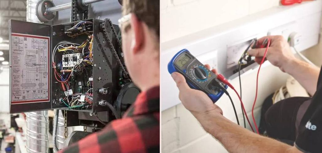
Before we dive into the steps, you might be wondering why you can’t just wiggle the wires and hope for the best. Visual inspections are great, but they only tell half the story. A sensor might look fine on the outside—clean lens, solid mounting bracket—but have internal circuit failure or a break in the wire that you can’t see inside the insulation.
A multimeter gives you X-ray vision, electrically speaking. It tells you if voltage is reaching the sensor and if the sensor is sending the right signal back to the motor unit. It’s the difference between guessing and knowing. Plus, it’s much safer than stripping live wires and sparking them together (please don’t do that!).
Step-by-Step Guide: Testing Your Sensors
Testing garage door sensors might sound technical, but it’s actually quite straightforward once you know what you’re looking for. You don’t need to be a master electrician to do this. You just need a basic digital multimeter, a few minutes, and a steady hand.
We are going to measure voltage (volts DC) and continuity. This will help us rule out whether the sensors are getting power and if the wiring running from the opener head to the floor is intact.
Step 1: Gather Your Tools and Safety Gear
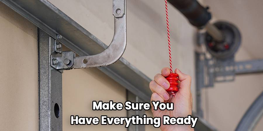
Before you start climbing ladders or touching wires, make sure you have everything ready. You’ll need a digital multimeter capable of reading DC voltage. Most basic models will work fine for this. You might also need wire strippers or a small screwdriver if you need to expose the copper on the sensor wires to get a good reading.
Safety first: While low-voltage garage door wires (usually around 24V or less) aren’t typically lethal like a wall outlet, you should still exercise caution. Make sure your ladder is stable. If you feel uncomfortable working with electricity at any point, it’s always okay to call a pro.
Step 2: Locate the Sensors and Identify Wires
Go to the bottom of your garage door tracks. You should see two sensors—one on the left and one on the right. One is the “sending” eye (usually has an amber or orange light), and the other is the “receiving” eye (usually has a green light). They work by shooting an invisible beam across the opening.
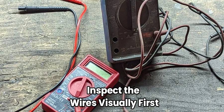
Follow the wires coming out of the back of each sensor. They usually travel up the wall and across the ceiling to the main opener unit. Inspect the wires visually first. Are there staples pinching them? Did a rodent chew through the insulation? If you see obvious damage, you might not even need the meter—you just need some electrical tape or new wire.
Step 3: Set Your Multimeter to DC Volts
Turn on your multimeter. You want to select the “V” with a straight line and a dashed line above it (this symbol represents Direct Current or DC). If your meter isn’t auto-ranging, set it to the 20V or higher setting. Garage door systems typically operate on low voltage, often around 5 to 6 volts DC at the sensors, though some systems vary.
Take your black probe and plug it into the “COM” port on the meter. Plug the red probe into the port marked “V” or “Volts.”
Step 4: Measure Voltage at the Sensor Wires
This is the critical part where we determine if power is reaching the bottom of the door. You need to access the exposed metal of the wires connected to the sensor. If the wires are connected with wire nuts, unscrew them temporarily. If they are spliced, you might need to undo the electrical tape.
Touch the red probe to the wire that corresponds to the positive connection (often the striped or solid white wire, depending on the brand like LiftMaster or Genie) and the black probe to the white or ground wire.
What to look for:
- Reading around 5-6 Volts: This is a good sign. It means power is traveling from the motor head all the way down to the sensor.
- Reading near 0 Volts: If you get nothing, the issue isn’t the sensor itself—it’s likely a break in the wire somewhere between the ceiling and the floor, or the opener board itself is bad.
When you are learning how to test garage door sensors with multimeter equipment, remember that consistent voltage is key. If the numbers are jumping wildly, you might have a loose connection.
Step 5: Test the Wires for Continuity
If you found zero voltage in the previous step, you need to find out if the wire is broken. This is called a continuity test.
- Disconnect the sensor wires from the opener motor head (up on the ceiling) and from the sensor itself.
- Twist the two wires together at one end (e.g., at the sensor end).
- Go to the other end (the opener end).
- Set your multimeter to the continuity setting (looks like a sound wave or WiFi symbol).
- Touch one probe to each of the two wires.
The result:
- Beep: If the meter beeps, the wire is intact. The loop is closed.
- No Beep (OL): If the meter is silent or displays “OL” (Open Loop), the wire is broken somewhere inside the wall or conduit. You will need to replace the wiring run.
Step 6: Check Sensor Functionality While Connected
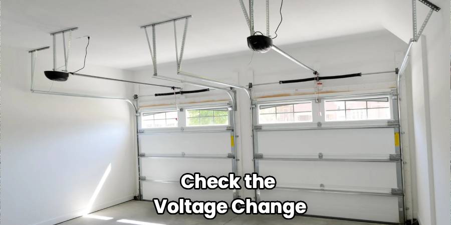
Reconnect everything. If you have confirmed you have voltage, but the garage door still won’t close, check the voltage change when the beam is broken.
Hold your probes on the sensor terminals again (carefully, don’t short them!). Have a helper wave their hand or an object in front of the sensor eye to block the beam.
On many systems, the voltage reading should drop or change significantly when the beam is obstructed. If the voltage stays exactly the same whether the beam is blocked or not, the “receiving” sensor may be stuck or defective. It’s failing to signal the “obstruction” state to the motor.
Frequently Asked Questions
Even with a multimeter in hand, garage door systems can be tricky. Here are some of the most common questions people ask when dealing with garage door sensor troubleshooting.
Can I bypass the sensors to close the door?
Technically, you cannot permanently bypass safety sensors on modern garage doors manufactured after 1993. It is a federal safety regulation. However, in an emergency, you can usually force the door to close by pressing and holding the wall button continuously until the door is fully down. Releasing the button before it closes will cause it to reverse. This is a temporary fix, not a solution.
What if the lights on my sensors are off?
If the LED lights on both sensors are completely dark, it usually indicates a power issue. This brings us back to the multimeter test. Check the voltage at the motor head terminals first. If there is power at the motor but not at the sensors, you have a broken wire. If there is no power at the motor terminals for the sensors, your logic board inside the opener might be fried.
Why does my door reverse immediately?
This is the classic symptom of a sensor issue. If the door starts to go down, stops, reverses, and blinks the overhead light (often 10 times), the opener thinks something is in the way. If the path is clear, it means the sensors are either misaligned or faulty. A simple garage door safety sensor test involves checking if the green light on the receiving sensor flickers. If it flickers, realign the eyes until it glows solid.
Do different brands have different voltage readings?
Yes. While the process is similar, the specific voltage can vary.
- Chamberlain/LiftMaster/Craftsman: Typically use a two-wire system where the voltage pulses. You might see around 5-6V DC.
- Genie: Older models handled voltage differently, but modern ones are similar.
Always consult your owner’s manual if you are getting weird readings like 20V or 1V.
Can sunlight affect my garage door sensors?
Absolutely. This is a surprisingly common source of garage door sensor problems. If the sun is shining directly into the “receiving” eye lens, it can blind the sensor. The infrared beam gets washed out, and the door thinks there is an obstruction. You can test this by holding a piece of cardboard to shade the sensor. If the door closes fine with the shade, you can buy small sun shields or simply swap the left and right sensors so the receiving eye (green light) is on the shady side of the garage.
Conclusion
Dealing with a garage door that won’t close is a hassle, but it doesn’t always require an expensive service call. By taking the time to verify your wiring and hardware, you can save money and gain peace of mind knowing your family is safe.
Remember, learning how to test garage door sensors with multimeter tools is the most definitive way to diagnose the problem. It separates a simple misalignment issue from a complex electrical failure. Whether it’s a broken wire, a fried circuit board, or just a sensor that has seen better days, the multimeter gives you the answer.
So grab your tools, follow the steps, and get that door moving again. Good luck!